Standard ignition curve including vacuum advance
In most cases, a standard engine uses both centrifugal and vacuum advance. In the graph below, the centrifugal curve is shown as a solid line, while the vacuum curve is shown as a dashed line. In both cases, two lines are shown. This is the margin within which the actual curve should fall. For our curve calculation, we take the middle. Note that the curve in the graph is based on ignition RPM; in the app, we use crankshaft RPM.
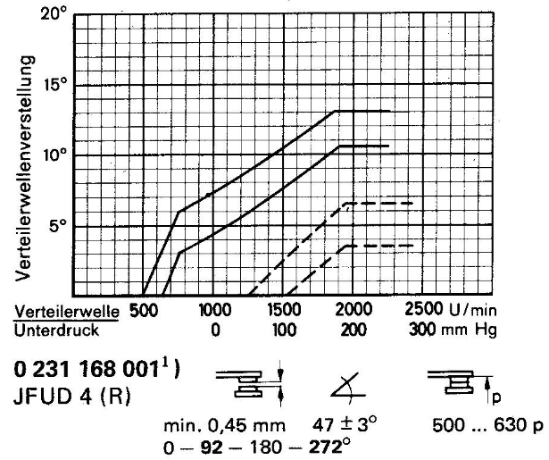
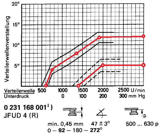
First, determine the break points. In the graph below, the points are marked.
Centrifugal points:
- 0° @ 600 rpm
- 4° @ 750 rpm
- 8° @ 1350 rpm
- 12° @ 1900 rpm
Vacuum points:
- 0° @ 80 mmHg
- 5° @ 200 mmHg
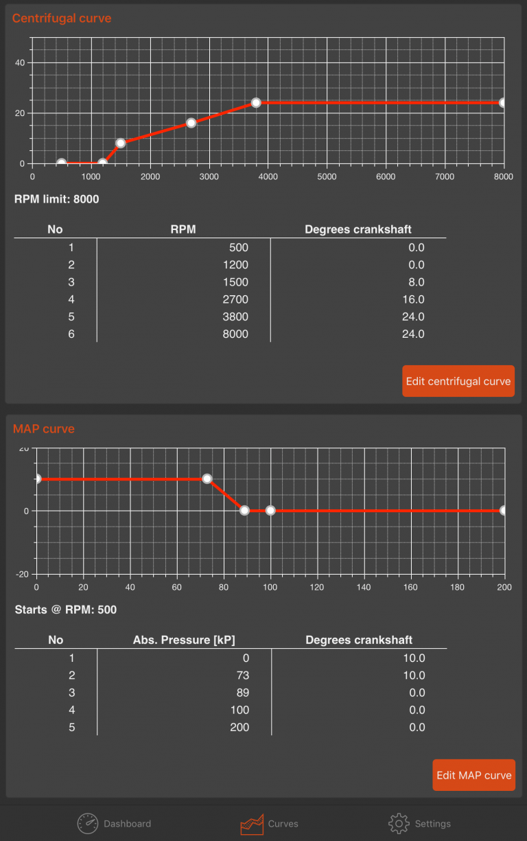
Now we begin converting the centrifugal points to crankshaft values. Both the RPM and the degrees must be doubled to get the correct values:
- 0° @ 600 rpm --> 0° @ 1200 rpm
- 4° @ 750 rpm --> 8° @ 1500 rpm
- 8° @ 1350 rpm --> 16° @ 2700 rpm
- 12° @ 1900 rpm --> 24° @ 3800 rpm
Regarding the vacuum curve, this is slightly more complex. The 123ignition works with absolute pressure instead of relative pressure. The advantage of absolute pressure is that it also works when driving at high altitude. With relative pressure, you would need to manually adjust the ignition when driving in the mountains, for example.
Note: The values in this original Bosch graph are displayed in mmHg; 123ignition uses kPa. First, we must convert the values from mmHg to kPa, and the distributor degrees to crankshaft degrees. Conversion: kPa = mmHg × 0.133322 (Tip: search Google for "mmHg to kPa conversion").
- 0° @ 80 mmHg --> 0° @ 11 kPa (relative vacuum)
- 5° @ 200 mmHg --> 10° @ 27 kPa (relative vacuum)
Next, we must convert the relative values to absolute values. Atmospheric pressure at sea level is 100 kPa, which is our baseline. All values below 100 kPa are vacuum (negative pressure); all values above 100 kPa are positive pressure. In this case, we have a vacuum curve, so the result is:
- 0° @ (100 kPa – 11 kPa =) 89 kPa (absolute pressure)
- 10° @ (100 kPa – 27 kPa =) 73 kPa (absolute pressure)
The curve can be programmed as shown in the image below.
Boost retard (turbo boost)
In a boost retard (turbo) situation, the centrifugal curve is set the same way as for a standard ignition curve.
Regarding the boost retard curve itself, this is a bit more complex. 123ignition works with absolute pressure instead of relative pressure. The advantage of absolute pressure is that it also works when driving at high altitude. With relative pressure, you would need to manually adjust the ignition when driving in the mountains, for example.
Note: Turbo boost is often indicated in PSI or bar; 123ignition works in kPa. 1 bar = 100 kPa, so this calculation is straightforward. PSI is converted to kPa like: kPa = PSI × 6.89476 (Tip: search Google for "PSI to kPa conversion").
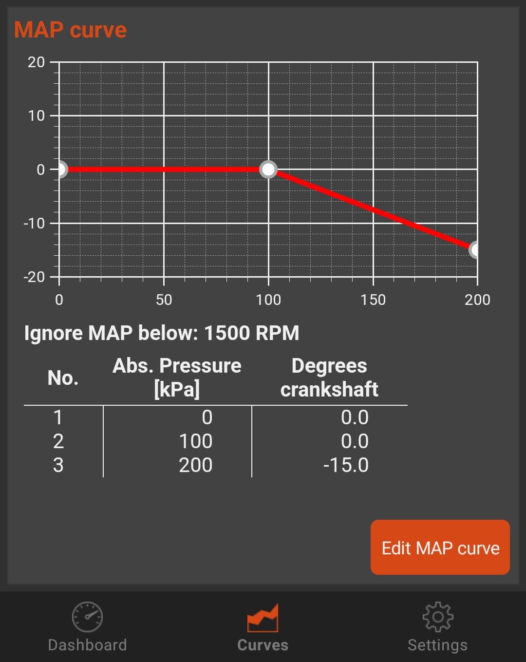
The rule of thumb is that at 1 bar (= 100 kPa) of turbo boost, the ignition must be retarded by 15°. Absolute pressure is then 100 kPa atmosphere + 100 kPa overpressure = 200 kPa
- 0° @ 100kPa
- -15° @ 200kPa
This can be programmed as shown in the image below:
Vacuum retard
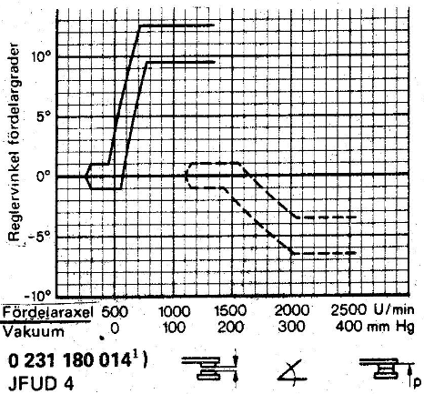
In the graph below, you will find two curves. The upper curve is the centrifugal curve. Ignition timing will increase as engine RPM increases. The lower curve is the vacuum curve; in this case, it is not a vacuum advance curve but a vacuum retard curve. This means that ignition timing is retarded when vacuum increases (i.e. when pressure decreases).
In both cases, two lines are shown; this is the margin within which the actual curve should fall. For the calculation of our curve, we take the middle. Note that the curve in the graph is based on ignition RPM; in the app, we use crankshaft RPM.

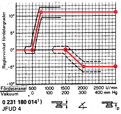
First, determine the breakpoints. In the graph below, the points are marked.
Centrifugal points:
- 0° @ 500 rpm
- 11° @ 750 rpm
Vacuum points:
- 0° @ 200 mmHg
- -5° @ 310 mmHg
Now we begin converting the centrifugal points to crankshaft values. Both the RPM and the degrees must be doubled:
- 0° @ 500 rpm --> 0° @ 1000 rpm
- 11° @ 750 rpm --> 22° @ 1500 rpm
Regarding the vacuum curve, this is slightly more complex. 123ignition works with absolute pressure instead of relative pressure. The advantage of absolute pressure is that it also works at high altitude. With relative pressure, you would need to manually adjust the ignition when driving in the mountains, for example.
Note: The values in this original Bosch graph are displayed in mmHg; 123ignition works in kPa. First, convert mmHg to kPa and distributor degrees to crankshaft degrees. mmHg is converted to kPa like: kPa = mmHg x 0.133322 (Tip: search Google for "mmHg to kPa conversion").
- 0° @ 200 mmHg --> 0° @ 27 kPa (relative vacuum)
- -5° @ 310 mmHg --> -10° @ 41 kPa (relative vacuum)
Next, we need to convert relative values to absolute values. Atmospheric pressure at sea level is 100 kPa, so that’s our baseline. All values below 100 kPa are vacuum (negative pressure); all values above 100 kPa are (positive) pressure. In this case we have a vacuum curve, so our result will be:
- 0° @ (100 – 27 =) 73 kPa (absolute pressure)
- -10° @ (100 – 41 =) 59 kPa (absolute pressure)
Because we are using vacuum retard instead of advance, a new challenge arises. The graph below shows that only the orange areas can be programmed. In the vacuum range, normally only advance is applied; in overpressure, retard is applied (turbo/boost retard).
To ensure that we can still use vacuum retard, a trick must be applied. We lift the entire vacuum curve by the maximum number of degrees we want to retard. In addition, the following data must be entered: 10° @ 99 kPa. With this trick, the unit knows that the entire curve is lifted by 10°. Atmospheric pressure (100 kPa) is also treated as 10°. The graph then looks as follows.
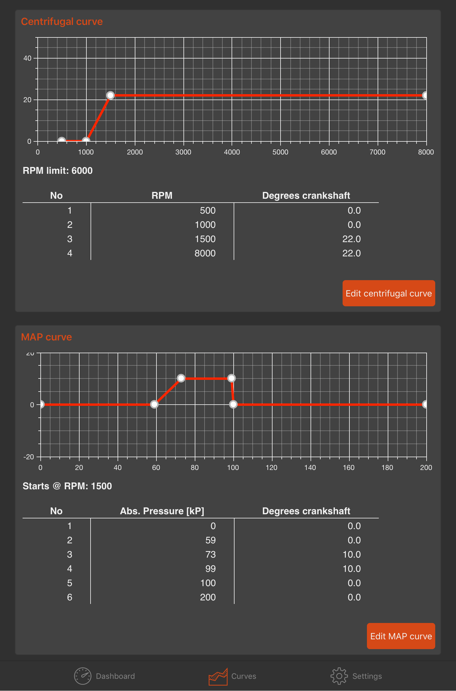
In this case, the unit has a standard 10° of advance timing. This timing advance will decrease as vacuum increases. This is exactly what vacuum retard is!
Note: The ignition must be rotated (retarded) by 10° to correctly set the total timing.